Description
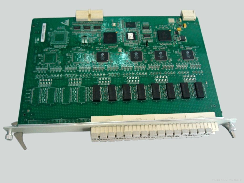
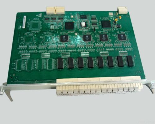
The PD2D card is a 32 xE1 electrical interface board that is installed in the Metro1000 chassis
Working principle and signal flow
Receive Direction
The interface module accesses an E1 signal and sends the E1 signal to the decoding module. The decoding module decodes the E1 signal to restore the HDB3 data signal and clock signal, and sends the signals to the mapping module
The mapping module asynchronously maps the E1 signal into a C-12 signal, adds the path overhead to the C-12 signal to form a VC-12 signal, adds the pointer to the VC-12 signal to form a TU-12 signal, multiplexes the TU-12 signal to form a VC-4 signal, and finally sends the VC-4 signal to the cross-connect unit
Transmit Direction
The demapping module demaps the VC-4 signal from the cross-connect unit, extracts the binary data and clock signal from the VC-4 signal, and sends the binary data and clock signal to the coding module. The coding module codes the signals and outputs the E1 signal through the interface module
Logic Control Module
This module communicates with the SCB. This module reports the board information, alarms, and performance events to the SCB, and receives the configuration command issued from the SCB
Power Unit
This unit provides DC power for all the modules of the board

 Search
Reviews
There are no reviews yet.